Among the most under-appreciated components in any audio system are the speakers. You could be using the best source unit on the planet, an amazing amplifier, and the most esoteric of interconnects and speaker cables – but if you don’t have great speakers, you still won’t have great sound. Your speakers are the only link between your electronics and your ears, so choosing great speakers is critically important to reproducing great sound. This article discusses what you get when you spend more money on speakers.
More Power Handling
Several factors limit the ability of a speaker to convert an electrical signal into speaker cone motion. One such limit is thermal capacity – just how much heat the voice coil, tinsel leads, former and cone can handle before one of them fails. Heat is the number-one enemy of speakers. Most of the power you send to your speakers is converted to heat rather than to sound – in fact, probably 95% or more is converted to heat.
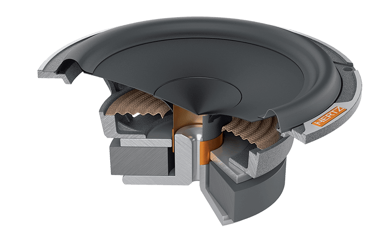
As the quality of speakers increases, you often encounter a larger voice coil and better cooling technologies. These features, coupled with tighter tolerances around the voice coil, result in a speaker that can absorb more energy without failing.
More Excursion
Often tied directly to how much power a speaker can handle is the distance the speaker cone can move forward or back. This specification is called excursion. For most speakers, the specification for excursion is called Xmax. Xmax is the distance the cone can move in one direction without the voice coil moving out of the magnetic field, and the measurement is typically provided in millimeters.
A second and often equally important specification is Xmech or Xsus. These specifications describe the physical limit of how far the cone can move, based on the design of the suspension (spider and surround). A speaker can be pushed past the Xmax limit, but as this happens, distortion occurs. When a speaker cone reaches its physical excursion limit, distortion will spike even higher. When it comes to speakers, there is no good distortion, so operating them within their physical limits is critical to producing accurate sound.
Why is excursion important? When combined with the ability to handle more power, a “better” speaker will play louder when provided with more power. The same features also help to reduce a phenomenon called power compression. Power compression is a reduction in the efficiency of a speaker as its components heat up. The key drawback to power compression is that when the music gets quieter, you turn the volume up, thereby sending more power to the speaker and accelerating the heating effect. In no time, the speaker will fail.
Excursion Linearity
 It’s one thing for a speaker to have good power handling and excursion characteristics. It is equally important that the speaker remains linear throughout its excursion-based operating range. All speakers change in their characteristics as excursion increases – a great speaker minimizes these.
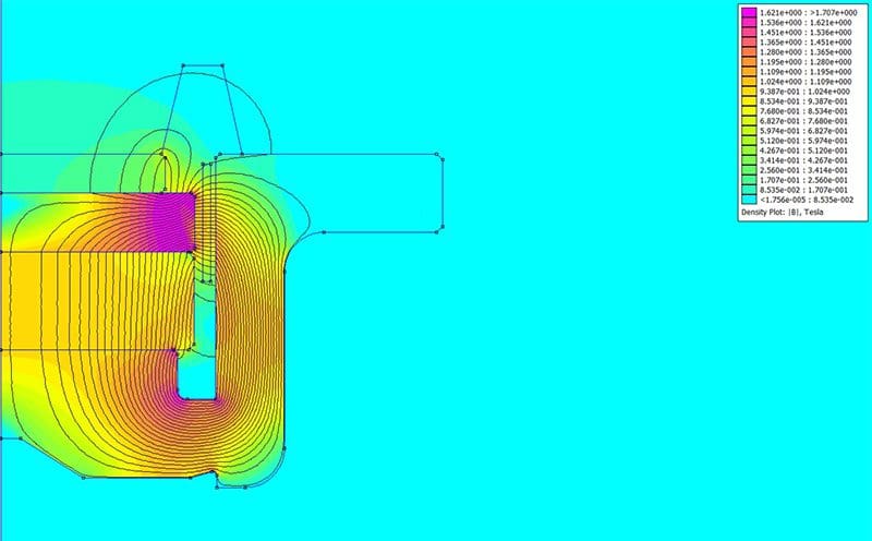
Let’s look at a common problem with “simple speakers.” One of the characteristics that limit the high-frequency response of a woofer or midrange driver is inductance. The voice coil of the speaker has some natural inductance because, well – it is a coil of wire. This inductance is increased when we place the voice coil around the T-yoke of a speaker.
This is where the problem occurs: As the coil moves forward, some of it may leave the T-yoke, which will reduce inductance. As the coil moves rearward, inductance may increase. The result is that the speaker has different frequency responses depending on where it is within its range of excursion. Truly excellent speakers use technologies to minimize these effects. The result are speakers that sound just as good at low to moderate drive levels as they do when being pushed hard.
More Frequency Response
This is a bit harder to describe, because sometimes the improvement from a basic to a mid-priced speaker, or a mid-priced speaker to a high-end one, is extended frequency response. More often, it’s smoother frequency response. Better-quality speakers are, ideally, designed to reduce distortion caused by cone resonances, suspension nonlinearities and magnetic field imbalances. As you spend more on speakers, you will see that peaks in their frequency response, especially in the midbass region, are tamed.
Many great speakers still exhibit some cone resonances at high frequencies. As long as the speaker you are using in the adjacent band will play low enough, those peaks are not critical.
Reduced Distortion
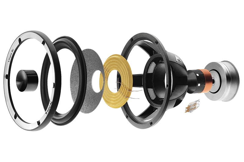 When a speaker designer combines an appropriately damped and rigid cone with a carefully designed motor and suspension, the result is a speaker that produces less distortion. Some distortions are very subtle, while others are quite pronounced. Speakers exhibit both even- and odd-ordered harmonic distortions, depending on what component or design issue is to blame.
If you have read our article on distortion, then you know that it is the effect of adding content that was not in the original program material. Harmonic distortion results in even or odd multiples of a specific frequency.
When you hear an amazing speaker, the difference between it and an average speaker is clarity. Smooth frequency response and a lack of distortion make each sound the speaker produces more faithful to the recording. Voices will sound more realistic. Instruments will sound more natural. Complex passages will become easier to understand.
It is also critical to point out that distortions cannot be removed from a signal or sound once created. No amount of equalization can extract those harmonics. Yes, you can reduce their level, but you also reduce the level of original signal information at those same frequencies. The only solution is to use a speaker that does not introduce distortion.
The Right Tool for the Job
Another item that differentiates a good speaker from a great one is its design in terms of application. Let’s use a typical 6.5” midrange/midbass speaker as an example. If the speaker is designed to work in a typical door or rear deck-style installation, the Thiele-Small parameters for that transducer will be optimized for that application. If you attempt to put that speaker into a small kick panel pod that has only 0.1 cubic feet of air space, you will choke it. The low-frequency response will be dramatically reduced; typically, a bump in the midbass region will occur, and it will likely not sound very good. Most 6.5” speakers need an enclosure volume of about 0.6 cubic feet, and some want closer to 1.0 for smooth frequency response.
How do you look for a speaker designed for the right application? That is product knowledge that a properly trained mobile electronics retailer can provide. Do you need a midrange that will work in a small A-pillar pod? Do you need a woofer that will work in an infinite baffle application? Will your midbass driver be used with a subwoofer, or do you need one that will be the sole source of bass in the system? Knowing the intended application for a speaker ensures that the system designer will use it appropriately.
Are More Expensive Speakers Always Better?
Does price always determine performance? In the upper echelon of any audio industry, the rewards for spending exponentially more money diminish. That is to say, the improvement you get from spending $500 on a set of speakers as compared to $200 may not be as dramatic as the difference between $2,500 and $2,200.
Every speaker manufacturer wants you to buy their speakers. They all work hard to come up with great marketing programs to make you want to buy their products. Your goal in choosing an amazing speaker is to ignore the story and listen.
The best way is first to establish a reference. Listen to the best speakers you can find. Don’t worry about the price. You simply want to understand what is available. Then, choose your price point and listen to something in that range. If you can accept the differences, then proceed. If you can’t, re-evaluate your needs or your budget. You can’t get that extra level of clarity, dynamics and detail any other way.
This article is written and produced by the team at www.BestCarAudio.com. Reproduction or use of any kind is prohibited without the express written permission of 1sixty8 media.